 Ask an Engineer
Specifying actuators 101: Actuator know-how for machine design engineers, Part 1
By Andrew Zaske on October 8, 2020
It’s fall, and that means lots of folks go back to school. Even mechanical engineers may want to take a refresher course. If you’re designing a new machine, these tips on actuator know-how will simplify your process, plus we have lots of resources for you to consult.
For example, our eBook is a resource to help you specify electric linear actuators in your next machine design project. It’s available for download, and we have summarized its content in a two-part blog.
Part 1–This week’s blog will cover:
1. Selecting the right actuator: rod or rodless
2. 10 tips for specifying rod actuators (actually, 3)
3. Selecting the right actuator: Which screw?
Part 2—Next time we’ll review
4. Selecting the right actuator: Calculating actuator life (rod and rodless)
5. Motor selection: Servo or stepper (gearboxes)
6. Motor selection: Motor mounting (or Your Motor Here)
For full details, listen to our webinar, “Actuator know-how for machine design engineers”
Let’s get started….
Electric linear actuators are used throughout manufacturing, the process industries, material handling and many industrial applications to create motion in a straight line. When you need to specify an electric linear actuator, begin by answering these simple questions:
- What needs to be moved?
- How far and fast does it have to move?
- How much does the load weigh?
- How much space is available for the system?
- What are the force requirements?
The answers to these questions will make actuator selection easier and lead you to the initial decision of whether to specify an electric rod actuator or a rodless electromechanical actuator.
1. Selecting the right actuator: Rod vs rodless actuators
(content provided by Kenny Green, applications engineer, Tolomatic)
One of the first steps to selecting electric actuators is to choose between a rod-style actuator and a rod-less electromechanical actuator. The main difference between the two is that a rod-style actuator has an extend/retract rod, similar to a hydraulic cylinder. A rod-less actuator has a slide that moves along the length of extrusion, similar to a pneumatic slide.
Rodstyle actuators typically provide higher forces and are designed for pushing, pulling, or pressing applications. They also provide ingress protection without the need for a shield.
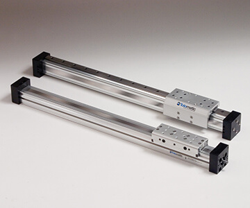
Rodless actuators guide and support the load. They usually don’t require external guides for loads, and they are space-saving because the screw, or belt loop, is inside the unit (i.e., minus the extend/retract rod). Rodless actuators are smaller and more compact compared to rodstyle, and their belt design allows for higher travel speeds; up to 100 to 200 inches per second instead of 20 to 40 inches per second with rod style actuators.
Key design differences
Rodstyle actuators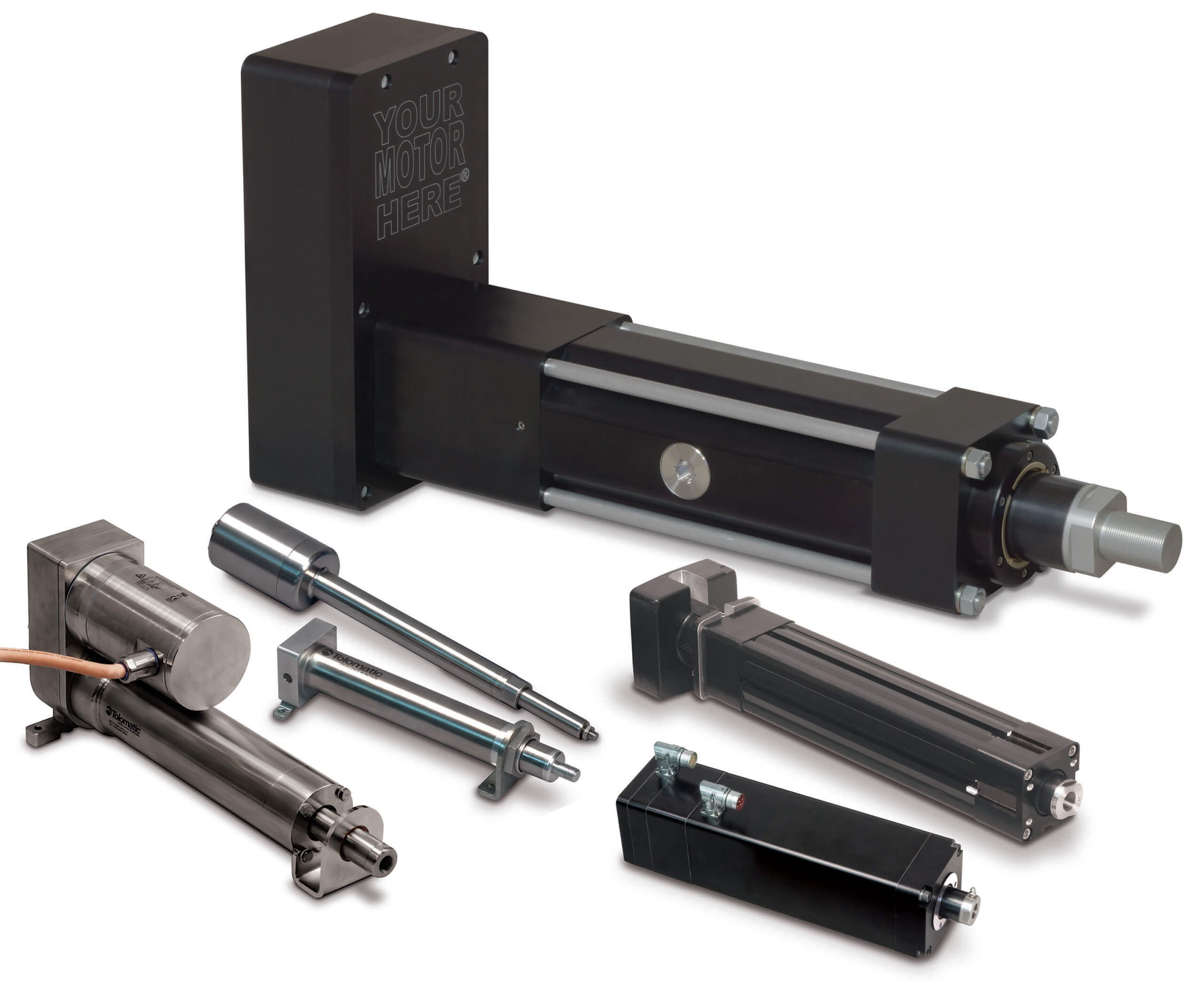
Rod-style actuators are screw-driven. A single bearing support for the screw helps guide the thrust rod. This allows for higher force applications because the thrust rod is directly in line with the screw and nut, allowing for significant force on the unit. The motor can be mounted in line (directly behind the actuator) or in reverse parallel with the actuator. This design has limits on stroke length and pushing forces. The maximum stroke length is about 60 inches; the longer the stroke, the slower the speed of the move, and the lower the maximum forces due to buckling concerns.
Rodless actuators
Rodless actuators can be screw-driven or belt-driven. Usually, the length and speed of the application determines the choice of screw or belt drive (i.e., force and velocity). A rodless design allows for longer lengths and faster travel compared to rod-style actuators. Screw-driven rodless actuators allow for greater force, but are limited on stroke length and speed. Belt designs allow for higher speed but lower force because force is limited by the belt. Belt-driven rodless actuators allow for stroke lengths up to 400 inches and up to 200 inches per second.
Application examples: rod vs rodless
Rodstyle actuators are ideal for hydraulic replacement: Motion simulators, bearing presses, mold ejectors and extruders. They can also be used for pneumatic replacement such as pivoting systems and gate/dooring positioning.
Rodless actuators are ideal for replacing pneumatic slides, such as for gantry systems, moving loads a long distance, cutting/slicing and space-constrained environments.
2. 10 tips for specifying electric actuators—actually, 3
(content provided by Jeff Brandt, applications engineer, Tolomatic)
Our classic white paper offers 10 tips for specifying actuators. But we’re going to break that down into three categories. Use this infographic as a checklist to make sure you’re covering everything you might need when starting to size your actuator:
1. Proper calculations = proper performance
2. Know your actuator’s capability
3. Environmental considerations
Proper calculations = proper performance
The key thing to remember is to calculate as precisely as possible for an electric actuator,. For another form of power, such as hydraulic or pneumatic cylinder, it’s typically a little easier to oversize the hydraulic or pneumatic system. But if you oversize an electric actuator, the cost increases rapidly. Make sure it’s sized for the exact needs.
You’ll also need to know velocity and critical speeds as well as the level of accuracy required.
2. Know your actuator’s capability
Here the key factor is duty cycle. Make sure the actuator fits the application. 100% duty cycle is very different than raising and lowering a desk once a day.
You should also avoid side loading by creating guides—designing in some compliance to allow self-alignment—as well as match the actuator to peak forces.
3. Environmental considerations
Know your operating conditions. Is there dust, paint or water spray? Some actuators are specifically designed for harsher environments.
To make specifying easier, download our checklists for sizing rod style and rodless actuators.
3. Selecting the right actuator: Screw selection
(content provided by Michael Witschen, applications engineer, Tolomatic)
There are plenty of variables to consider when sizing an electric actuator. One of the major elements is what screw to use. Each type of screw offers a different force range, life expectancy and speed, and that will affect your selection.
Key screw technologies
Ball screws and roller screws are two primary categories often used in rod style electric actuators.
Ball screws have a smaller overall contact surface (which limits their ability to absorb large loads), but the low-friction screw allows for speed and doesn’t create much heat. Ball screws are ideal for applications requiring high speed and positioning, plus they are lower cost compared to roller screws.
Roller screws have an increased contact surface area, which allows them to absorb larger loads. But more friction creates more heat. They are ideal for pressing and repeated stress applications. Roller screws will also typically provide a much longer working life expectancy.
Electric screw-driven technology
When you size your actuator, you will need to make selections based on some standard terminology. Tolomatic sizing charts include this information for each actuator. Your options include:
- Maximum stroke length in inches or centimeters
- Screw code: Type of screw (e.g., BN for ball nut and SN for solid nut)
- Turns per inch (lead): How many revolutions of the screw to get one linear inch of travel
- Lead accuracy (backlash): Especially important for repeated pressing applications.
- Maximum thrust: What the actuator itself, with the specified screw, is capable of. The limiting factor for what loads and forces can be applied with the specified unit and screw combination.
- Dynamic load rating: An industry standard used for calculating life expectancy.
This information will help get you started specifying your actuator. Our next blog post will cover:
4. Selecting the right actuator: Calculating actuator life (rod and rodless)
5. Motor selection: Servo or stepper (plus gearboxes)
6. Motor selection: Motor mounting (or Your Motor Here)
Tolomatic has many resources to help guide you through the process. And, you can always ask an engineer for help with your application.